Press Room Automation & Feed Fixtures Pvt. Ltd. manufactures automatic lines for circle cutting from coil with the aim of reducing the scrap quantity by exploiting the whole width of the coil.
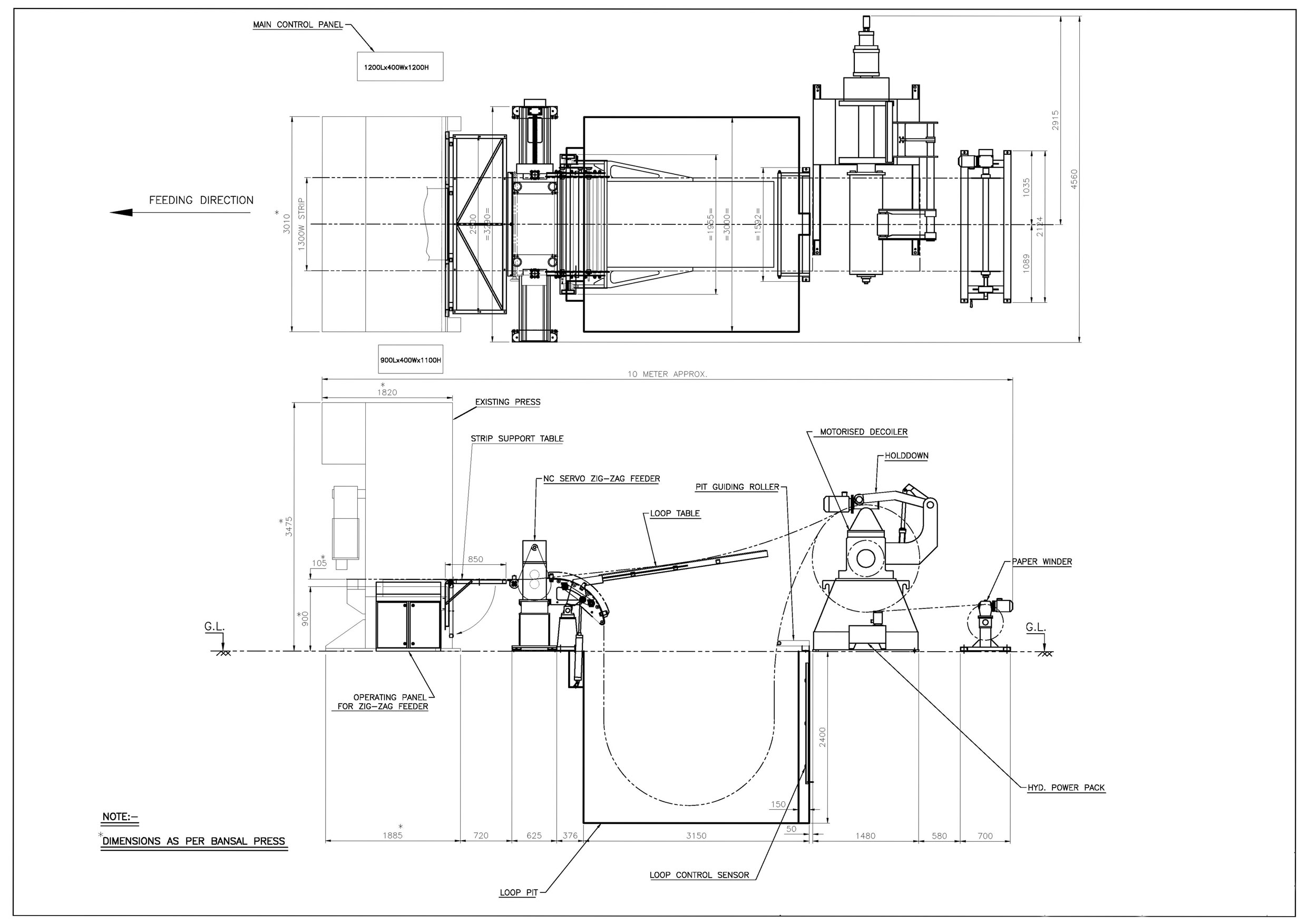
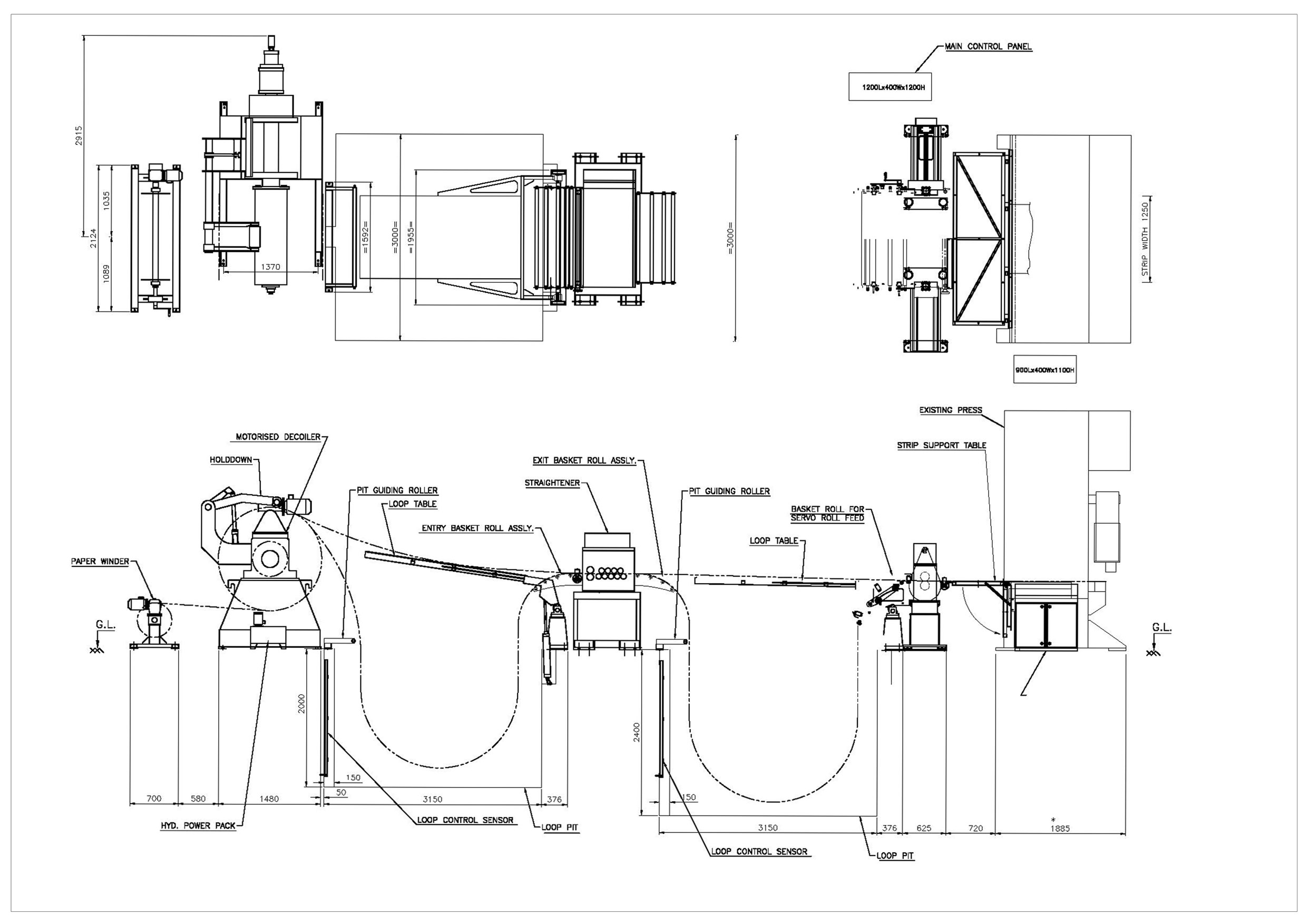
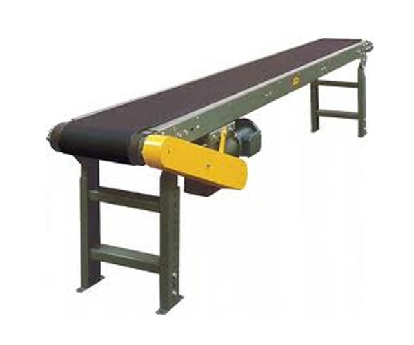
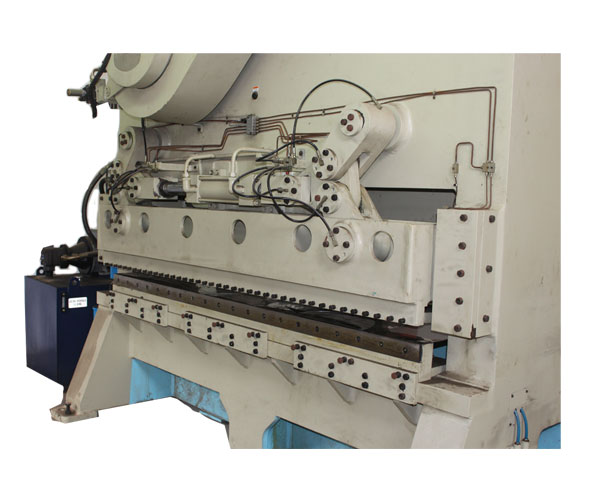
The technology used by Press Room is shifting of the coil below a fixed die. It is characterised by a good production capacity, high flexibility and low tooling costs. Line consists of decoiler with coil car, straightener, nc zig zag feeder, press, shear & stacker. Entire working sequence is directly managed from Control Panel which allows operator to have a single control of all the line functions.
The strip from the coil can have two movements, both NC servo controlled: the feeding movement (called longitudinal shifting) & the lateral movement (called transversal shifting). Thanks to these movements, each blanking is followed by the lateral movement of the coil of a programmed step and by the blanking of the next disk, up to the realisation of a row of blanked disks along the coil width. At the completion of the row, the strip is fed so that the blanking of a new row can start.
Press Room has designed special programme which automatically calculates position by depending on stock width & circle diameter. The program allows optimizing the material use, minimizing trimmings.
COMPLETE AUTOMATIC CIRCLE BLANKING LINE
EQUIPMENTS AS PER FOLLOWING :-
OPTIONAL EQUIPMENTS
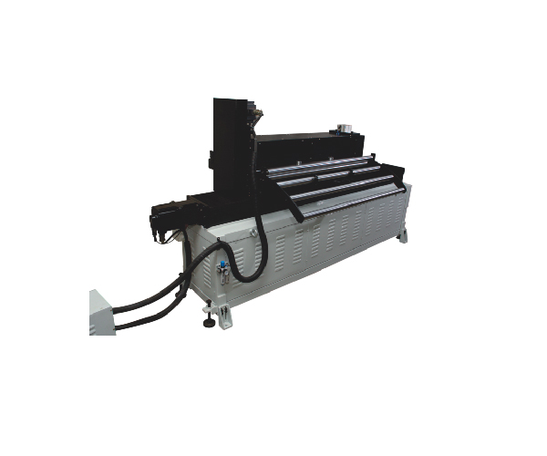
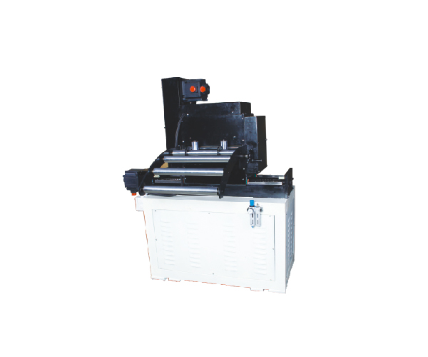
NC Servo Zig Zag Feeder
Designed for blanking out circles, zig/zag servo feeds can be programmed to perform from two to multiple rows / pattern, typically saving at least 8% in material costs.
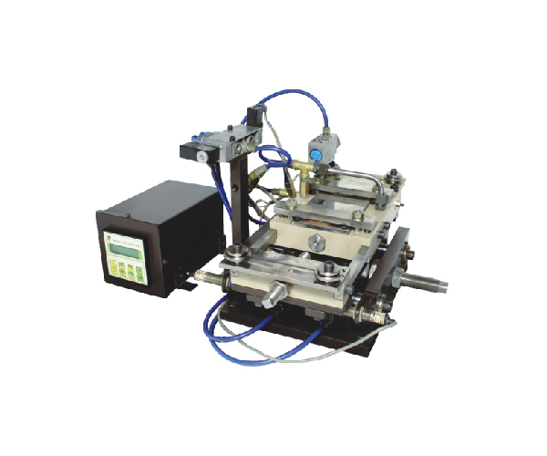
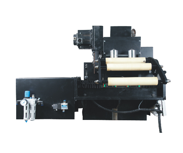
Pneumatic Zig Zag Feeder
Designed for blanking out diameters, pneumatic zig/zag can be adjusted to perform from two blanks, typically saving of 6% in material costs.
Servo Pneumatic Zig Zag Feeder
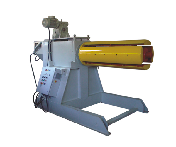
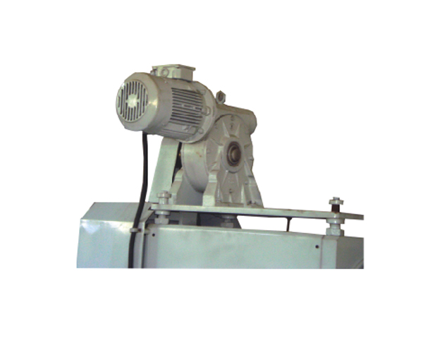
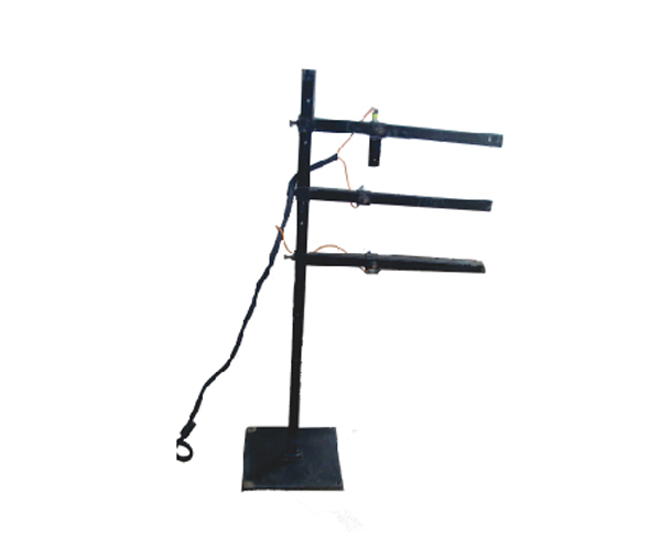
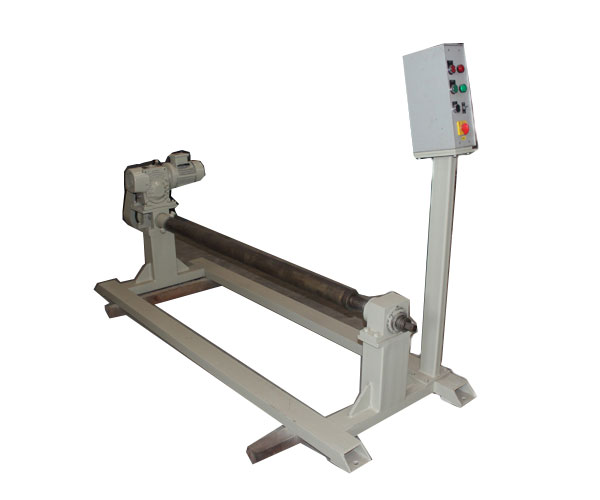
Motorised Decoiler
Width - 1300 mm/Coil Wt - 10 tons
Model - VD - 100
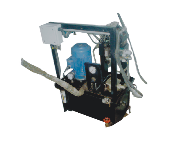
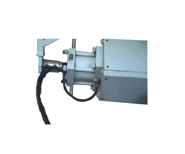
Motorised Decoiler with Hydraulic Jaw Expansion
Motorised Decoiler with Hydraulic Jaw Expansion
Four self centering coil-location jaws. with Hydraulic jaws expansion to provide stability and constant grip
The Spindle & Coil holding heads housed in mechnical & precised mechined housing & rotates on dust proofed sealed bearing heavy duty anti-friction bearings.
A.C. variable speed Drive system.
All motorised decoilers are through heavy duty gearbox, motor & friction drag brake.
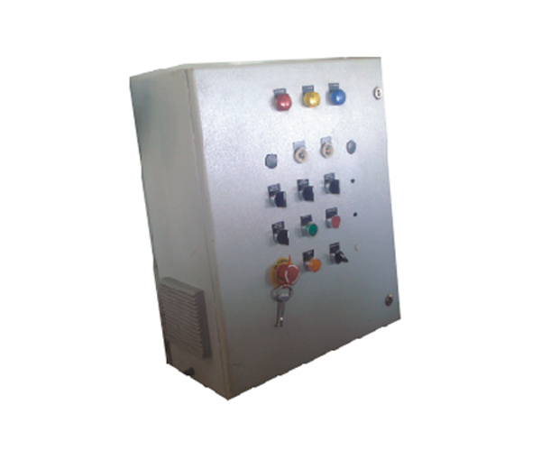
Control Panel with Suitable loop control system to maintain loop of coil.
Optional
Mechnical Jaw Expansion.
Coil hold-down (hydraulic/pneumatics) to claim down the strip & to hold the material
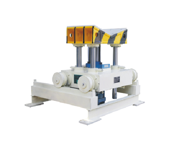
Coil car
Hydraulic or servo base movement for decoiler centering.
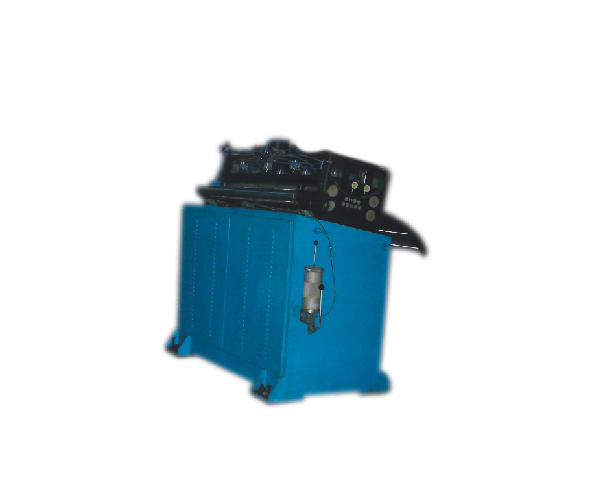
A Presicion straigntener head complete with straightening rolls, one set of input pinch rolls along with all bottom rolls driven through gearbox & suitable control panel with sensors. The control panel would control the feeding speed & loop.
Suitable lubricating points and tubing will be provided for manul lubrication.
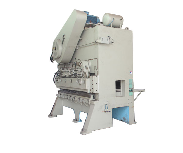
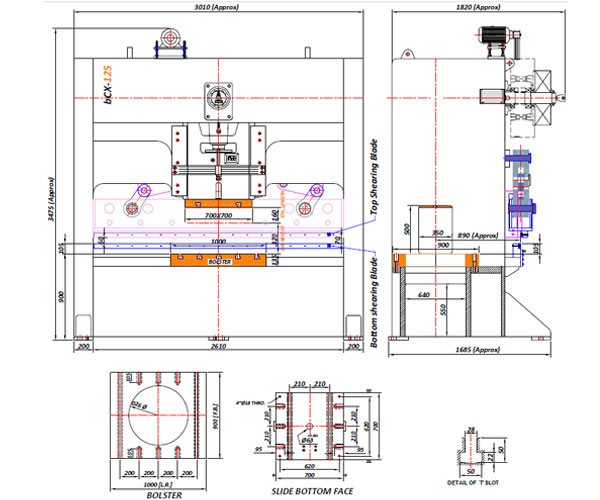
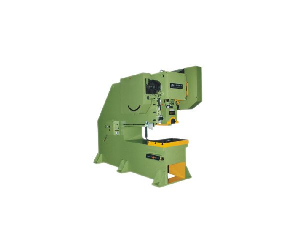
Single Point Suspension, Non-Inclinable, Geared, Single Action Press heaving tested steel plate fabricated H type structure with 6 point gibbing of slide, fitted with pneumatically operated combined single Disc friction clutch & Brake complete with electricals, control panel & production counter.
STANDARD ACCESSORIES
SR NO |
DESCRIPTION |
UOM |
DIMENSION |
1 |
Capacity |
Tonne |
125 |
2 |
Tonnage Rating Point |
MM |
5.0 |
3 |
Bolster Area |
MM |
1000 X 900 |
4 |
Bolster Thickness |
MM |
135 |
5 |
Stroke Length (Fixed) |
MM |
160 |
6 |
Die Height |
MM |
320 |
7 |
Slide Area |
MM |
650 X 650 |
8 |
Slide Adjustment |
MM |
90 |
9 |
Frame inside Gap |
MM |
2600 |
10 |
Floor to Top of Bolster |
MM |
900 |
11 |
Variable Speed |
SPM |
30 ~ 60 (full load @ 40) |
12 |
Main Motor |
HP X P |
15 X 4 |
13 |
Photo Electric Safety Guards |
SET |
Suitable to machine |
14 |
Bolster Opening |
MM |
As per requirement |
The above equipments are designed for Line speed of 12-25 Mtrs. Per Minute.
Models of higher capacity or higher or lower line speeds are available on request.
NC Servo Zig Zag Feeder Models
Model |
SZZ – AA200 |
SZZ – A300 |
SZZ – B300 |
SZZ – BH400 |
SZZ – B600 |
SZZ – C800 |
SZZ – C1300 |
Material Thickness |
0.1-1.5 |
0.3-2.0 |
0.3-3.0 |
0.3-3.0 |
0.5-2.0 |
0.3-1.5 |
0.3-1.2 |
Width |
50-200 |
100-300 |
100-300 |
150-400 |
200-600 |
250-800 |
400-1300 |
Circle Diameter |
20-105 |
30-159 |
30-159 |
40-212 |
60-320 |
80-427 |
100-695 |
SPM |
60-80 |
40-70 |
30-60 |
30-60 |
30-58 |
28-54 |
25-50 |
Pneumatic Zig Zag Feeder Models
Model |
PZZ – 100 |
PZZ – 150 |
PZZ – 300 |
Material Thickness |
0.5 – 1.5 mm |
0.5 – 2.0 mm |
0.5 – 2.0 mm |
Width |
0 – 100 mm |
0 – 150 mm |
0 – 300 mm |
Zigzag Indexing Pitch |
0 – 55 mm |
0 – 80 mm |
0 – 160 mm |
Stroke / Pitch / Feed Length |
0 – 100 mm |
0 – 150 mm |
0 – 300 mm |
SPM |
80 |
60 |
30 |
The above parameters are for the material having tensile strength 40kgf/mm² max.
Models of higher capacity or higher or lower line speeds are available on request.
Technical specifications are indicative and subject to change to suit end application.


